
UPDATED FOR MPLAB.X!!! How to make your own battery-powered datalogger using a PIC24F32KA microcontroller and a Bluetooth module

Objective
The idea is to develop a datalogger able to record temperature readings periodically, with a period defined by the user (from seconds to one year). The readings must be stored in an MicroSD card organized in files with their respective timestamp. The user must be able to push a button at any moment and see the current temperature on a LCD display during several seconds. Afterwards the datalogger listen for Bluetooth serial requests before turning back to stand-by mode (deep-sleep) again if the time for request expires. During the request time the user can download data files using an external Bluetooth adaptor. If no remote request is received within several seconds, the device turns back to deep-sleep mode. Each time the device is awake a LED is turned on and in some special situations it must produce beep signals with a buzzer, so the user has feedback of what is going on. The sound must be different if a operation has been right (high and short beep) than when something goes wrong (lower and longer beep). One example of a wrong operation is when the system proceeds to store data into the SD card but the card is not inserted in its slot.
The device must be powered by a small rechargeable 3.7V Li-Ion battery of about 1000mAh of capacity obtained from a mobile telephone. The power autonomy of the system must be enought to be used for long periods of time like months or even years depending of the adquisition period and the intervention of the user.
You don't have to worry if you don't have an LCD display like the one used in this project, or if you have it, but don't want to use the Bluetooth functionality. There are several conditional compilation labels different functionalities that you can comment in the PIC code. For example, if you just want to gather data in the SD for a period of time you can comment both labels (USE_LCD and USE_BT). If you also want visualize the current temperature you can comment out the USE_LCD label and if you need the Bluetooth functionality for transfering data files with an external device and visualize/configure the device remotely you need to comment out the USE_BT label.
I will save you time and put here all you need to download:
- Kicad Project files: download
- MPLAB.X Project: download NEW!!!. You can download the previous MPLAB v8 project here
- Python GUI interface: download
Architecture
The following figure shows the global architecture of the project. In the diagram I have not included the power system, because here I just want to show the devices that affect to its functionality as a full datalogger. As you can see, there are several devices interconected by several links which represent standard comunication buses or just normal digital signals. This project uses four standard communication buses: RS232, I2C, SPI and onewire.

And you can download here the Kicad project.
The microcontroller
The core of the system is the microcontroller where the firmware is executed to perform the task of the device. I have choosen a PIC24F32KA302 microcontroller from the Microchip PIC24 family because, despite its low flash memory size (32Kb flash for program and 2Kb of RAM), it has several features that makes it ideal for this project like Real Time Clock Calendar (RTCC), deep sleep mode (ultra low power consumption, 500nA with RTCC active), I2C, SPI, RS232, EEPROM (512 bytes), etc.
In our application, the microcontroller used will be most of the time in deep-sleep mode waiting for the next reading or for a user request. Therefore, it is very important to keep the power consumption as lowest as possible. We also need the RTCC functionalty to know the timestamp of the readings and to program an alarm that wakes up the microcontroller exactly when a measurement is needed. This microcontroller also supports a very low frequency crystal-based external oscillator (32Khz) which is very important in order to get an accurate and stable time measurement. It also has an ADC module that allows measuring internally its own power voltage, so we can know the battery level without any external component and conection.
The temperature sensor
The sensor used is the DS18B20 temperature sensor from Dallas Semiconductors wich can operate from 3.0 to 5.5V allowing the use of a Battery of 3.7V which is our case. It has a a measurement range from -55°C to +125°C and has a precission of ±0.5°C and a maximal resolution of 12bits. This means that it can distinguish a change in 0.0625°C with that resolution. The DS18B20 communicates with the microcontroller by onewire protocol and it is possible to connect an almost unlimited number of sensors in the same wire addressable by an address of 64bits. The DS18B20 has the possibility to be powered by the data line (parasite power) or use a separated VDD line to power the sensor, here we use the last option because in "parasite power" we need an additional MOSFET transistor. The VDD terminal of the device is permanently connected to the VCC power line of the datalogger but after a measurement the device enters in stand-by mode dropping the consumption to near 1uA, which added to the consumption of the microcontroller in deep-sleep with RTCC gives about 1.5uA. With this consumption a battery of 1000mAh could last up to 76 years. Of course, in the hypothetical case that the battery don't discharge by itself and don't loose capacity along the time and if the microcontroller never wakes up, but gives us an idea of the power wasting when the device makes nothing.
The SD card
The SD is used for storing the temperature readings with their respective timestamp. The readings are added to a "readings of the day" file which name is the date when the reading was taken (For example: 13_06_03.txt which means 03 of June of 2013). The SD is also used to host the "PARAMS.txt" file which contains among other things the name of the Bluetooth device and the sampling period (from seconds to one year). The libraries for SD card management used in this project allows up to 2GB of storage capacity which is enought for years of measurements. The communication between the microcontroller and the SD card is by SPI bus, which allows a simultaneous bidirectional flow of data at high speed up to 1MB/sec. The type of card used is the MicroSD Card using and adaptor to SD Card as a socket for the integration with the PCB.


The power line of the SD card is only activated when the PIC wakes up, so it doesn't consume energy from the battery in deep sleep periods.
The bluetooth module
The data can be transfered to an external device throught a HC-05 Bluetooth module which can be configured as a master or a slave. Since we want to connect our datalogger with a computer it must be configured as a slave. The communication between the microcontroller and the HC-05 is throught RS232 serial communication, either for configuration and communication with external devices. The configuration of the device is made only once by using AT commands as you can see in the datasheet. In normal operation, once the computer has paired with the bluetooth module of our datalogger, the microcontroller can communicate with the PC as if there is a wired RS232 serial port between them. In UBUNTU, to create the serial link /dev/rfcomm0 through bluetooth you have to edit the file /etc/bluetooth/rfcomm.conf as superuser and add the following entry:
rfcomm0 {
# # Automatically bind the device at startup
bind no;
# # Bluetooth address of the datalogger device. MODIFY IT CONVENIENTLY
device 00:13:02:20:93:39;
#
# # RFCOMM channel for the connection
# channel 1;
#
# # Description of the connection
comment "Datalogger device";
}
to discover which is the MAC address of the bluetooth device, once it is powered, plug in a bluetooth adaptor on your pc and execute:
>hcitool scan
Notice that the bluetooth board has a jumper. When it is set the bluetooth module is in configuration mode and will receive default configuration AT commands from the PIC at boot time. This must be done the first time, the configuration will keep stored in the EEPROM of the BT device and will not disapear even if you remove the battery. The following time the jumper must be removed to work in communication mode.
The HC-05 is transparent to the communication which simplifies very much the problem. I have defined a simple ASCII protocol between the datalogger and an external device which allows setting the RTCC clock and request data. In order to integrate the HC-05 with the main board a small PCB adaptor is used to transform its rectangle arranged pinout to a serial in line footprint.

As you can see in the schematic of the adaptor is quit simple. The HC-05 bluetooth module wired to a SIL-5 connector and a jumper with a 10K pull-down resistor attached to the Key configuration pin. As I have explained above, the jumper force the module to enter in configuration mode which means that you can send AT commands to the module throught the serial port. The most significant are the baud rate and the mode (master/slave). If the jumper connector is open the module works in transparent mode. Here you can read a short and quick tutorial about how to use the HC-05 module.
The HC-05 consumes about 60mA when it is in "pairing" mode and about 38mA when it is already paired. This is the most energy consuming device in the datalogger, so it is very important to turn on the module only when it is going to be used, that is, when the user request download data from the datalogger. The PIC microcontroller activates its power line before initiating the comunication with the external device and after transferring the data turns it off.
The LCD display
The LCD display is used in this project to visualize the current temperature as well as the status of the device when necessary. The LCD displays use to have a very low energy consumption because the visualization is based on reflecting or not the external light that arrives to the display. It doesn't emit active light saving much more energy than other kind of displays like for example LED displays. The display used in this project is the JX5080PHR which is 2 digit x 7 segments with dots. The digits are quite big to be seen easily and with only 2 digits the temperature can be shown in sequence, first the degrees and then the next two decimals. As you can see in the schematic of the display circuit the LCD display is controlled by a PCA9552 16bit I2C LED driver chip which in this case instead of controlling LEDS controls LCD segments.


The whole LCD board consumes about 1 mA when it is active which is quite low but its power line is activated by the microcontroller only when some data must be displayed.
The main circuit
Here is the schematic of the main circuit

An external 38KHz crystal oscillator provides an accurate time sincronization even in deep-sleep mode. There are also two activable power lines labeled VCC_BT and VCC_PER respectively. They are activated by the PIC with the signals labeled PWR_BT and PWR_PER. The VCC_PER is the power line of the SD card and the LCD display and is activated throught a PEMD9 NPN-PNP double transistor. The PWR_BT is for the HC-05 bluetooth module and is activated throught a PEMD10 NPN-PNP double transistor which has lower polarization resistors than the PEMD9, so it can provide more current keeping the voltage level 0.2V below the battery voltage. The NPN-PNP double transistors are encapsulated in SOT666 package which is extremely small. You should be very carefull checking the copper footprint after making the PCB board and when soldering it. The rest of the circuit are just switches, connectors and pull-up/down resistors.
The main board consumes about 10-15 mA in "wake-up" mode and just 500nA in deep-sleep. The battery used is a Nokia BL-5C Li-ION 3.7V with a capacity of 1020mAh. This model of battery is ideal for this project and make it possible to keep the device working for long periods of time without charging.

The firmware
The firmware has been programmed using the XC16 compiler and the MPLAB.X IDE. You can download the MPLAB Project here.
Before trying to compile it ensure that the compiler has the optimization option -Os activated in Project properties -> xc16-gcc -> optimizations -> optimization level = s , otherwise the compiled code won't fit on the program memory of the device.
The code is widely commented and it is also documented in HTML with doxygen in the folder called "documentation"
The code is organized in such a way that you can compile it depending on the hardware you have. There are 3 labels for conditional compiling: USE_LCD, USE_BT and USE_SD. For example if you don't have an LCD display you can comment the USE_LCD label and compile it. You won't be able to see the current temperature but the datalogger still works and you can communicate with it by Bluetooth. If you don't have the Bluetooth module you can comment the USE_BT label and you won't be able to communicate with the device but the parameters defined in the SD card will define the functioning of the datalogger. You can copy the captured data from the SD card to you computer for further analysis. The most extreme case is when you don't have any of the 3 peripherals, just the base board. In this case the datalogger will function with the default parameters and as a simple temperature monitor that activates an alarm when the default threshold temperatures are exceeded. You can combine the firmware compilation depending on which hardware you have.
The firmware is also organized modularly depending on the function. There are modules for the following functionalities: Analog to Digital converter, beep functions (buzzer), delays, ds1820 temperature sensor, eeprom read and write, 2x7 seg LCD control, I2C bus functions, oscillator, Real Time Clock and Calendar (RTCC), SD card functions and UART serial port. You are free to use any of these modules in your own projects. In the "include" directory there are several configuration files for most of the functionalities of the device. Check them if you are plannig to modify something in the design or in the behaviour of the device.
The PC software
The software in the PC side is programmed in Python. If you know python maybe you can translate it to other programming language like C/C++, Java, etc.
You can download the code here
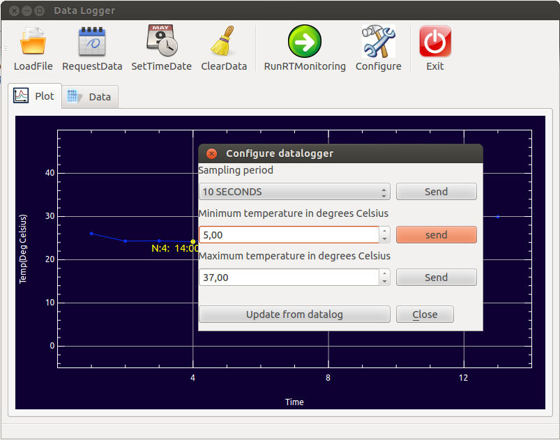
The next image shows how the GUI interface looks like. It is made using the PyQt libraries.

Plot of the captured data
By clicking in any of the points of the data plot the information realive to that capture is shown. As an example the image above shows the capture number 4 was taken al 14:00 and the temperature was 24.18 degrees Celsius.
Before trying communicate with the datalogger you must ensure that you have created the /dev/rfcomm0 port (see above) and that can be done once you have push the datalogger button when it request communication by showing the characters "CC" blinking. Once the link with the datalogger has been stablish the dataloggere will show the characters "SH". If the datalogger doesn't receive a command from the computer within several seconds it will switch off itself and the process must be re-done.
It is possible to configure the parameters on the datalogger's EEPROM like the sampling period, minimum and máximum alarm temperature. For doing that there is an option in the main button bar called "Configure" as it is shown in the next figure. By clicking in the "Update from datalog" button in the "Configure datalogger" dialog the data shown is updated with the current data stored in the EEPROM of the device.
There is a tab in the main window for showing the numerical data loaded so far, showing the ordinal number, timestamp, temperature and battery level of every capture.

The datalogger stores automatically the data organized in separated files for each day. For requesting data to the datalogger corresponding to an specific day you can click the "RequestData" button and a calendar will appear to ask you for the day. After clicking the day the application will download the readings of that day and will store them in a file locally in the PC inside the "data" folder. The name of the file is rather intuitive. Example: 16_03_14.txt will correspond to 14th of March 2016. At the same time the data is visualized in the plot and in the data table tab. You can visualize that data at any time without connecting with the datalogger just by loading that file with the "LoadFile" button.

I hope this blog will be useful for you or at least helpful for developping your own "low-power" or "battery-powered" applications.